Flotherm中加入热管模型后收敛困难。
热管具有非常高的有效导热率。因此,当涉及使用温度变量收敛时,可能产生问题。
为避免这些问题,建议用户:
- 使用双精度求解器(double precision solver “求解器控制”选项卡)
- 使用“共轭残差”选项(conjugate residual “求解器控制”选项卡)
- 将温度的错误时间步长增加~x20(在“求解器控制”选项卡下)
- 定义新的环境变量FLOMAXITFORTEMP并将其设置为等于任何值
Collapsed object辐射
Radiation is calculated based on the temperature difference between objects. Therefore for the software to compute these temperature differences it must know the temperatures of the objects partaking in the Radiative exchange. In fixed temperature cuboids (collapsed or uncollapsed) the temperature of the object is explicitly set. Therefore these objects partake in Radiation but can only pass heat to other objects cooler than themselves. They cannot become warmer or cooler because their temperature is fixed by you. Objects set to have a fixed heatflow give out energy to the neighbouring grid cells but do not have a temperature calculated within them. Therefore there is insufficient data for the software to compute its radiation calculation and therefore they will not partake in the radiative exchange. Collapsed objects can only take part in the radiation calculation if they are set to be fixed temperature. If set to be conducting they cannot take part in the radiation calculation because they don't have grid-cells within them to store the temperature data.
Note: These objects will all act as obstructions to radiation, inhibitting the view factor between other radiating objects.
Open Domain
运行辐射模型时,开放边界如何影响辐射传输?是否计算出交换因子?什么是辐射温度?
-
All radiating geometry inside the domain will radiate towards “infinity outside the domain”, the domain boundaries.
-
Therefore exchanges factor are calculated.
-
Domain boundaries are ideally “black”.
-
Radiation is always a two-way process. Hence, if the radiation temperature of the domain boundary is higher than the body temperatures inside there will be a positive net radiation heat flow into the domain and heat will be added. If the radiation temperature is lower than the body temperatures heat will be extracted from the system.
-
The temperature used to calculate the radiation of each domain boundary is set in the Project Manager in
o [Model Setup] – Default Radiant Temperature
-
Ambient Attributes may be used to overwrite the above settings with Radiation Temperature other than the Default Radiant Temperature. You may use different Ambient Attributes for different sides and hence different Radiation Temperatures on different sides of the domain.
-
Domain boundaries which are set to “Symmetry” are adiabatic. To prevent violation of the energy conservation, one side will be opened to radiation transfer (but only for radiation transfer!) automatically. In this case there will be a warning displayed in the Message Window.
-
域内的所有辐射几何体都将向“域外无限域”(域边界)辐射。
-
因此计算交换因子。
-
域边界理想地是“黑色”。
-
辐射始终是一个双向过程。因此,如果畴边界的辐射温度高于体内的体温,则将有正的净辐射热流进入区域并且将加热。如果辐射温度低于体温,则将从系统中提取热量。
-
用于计算每个域边界辐射的温度在项目中设置[Model Setup] – Default Radiant Temperature
-
环境属性可用于使用除默认辐射温度之外的辐射温度覆盖上述设置。您可以针对不同侧面使用不同的环境属性,从而在域的不同侧面上使用不同的辐射温度。
-
设置为“对称”的域边界是绝热的。为了防止违反节能措施,一方将自动开放辐射传输(但仅用于辐射传输!)。在这种情况下,消息窗口中将显示警告。
求解
Insufficient Memory < Exchange Factor Calculation performed abnormal exit >
The total radiating faces is above the limit.
The number of radiating faces is limitating to 120000 radiating faces by default. If the number of radiating surfaces exceeds this value, an exception is thrown and the EFG aborted.
To increase the number of radiating faces using Environment variable, you can set
System environment variable: EFGFACELIMIT
System environment value: Number
When the calculation is done, the number of radiating faces can be found on the first line of the following file: BaseSolution\Exchange\facelist (Open with Wordpad)
Collapsed object辐射
Radiation is calculated based on the temperature difference between objects. Therefore for the software to compute these temperature differences it must know the temperatures of the objects partaking in the Radiative exchange. In fixed temperature cuboids (collapsed or uncollapsed) the temperature of the object is explicitly set. Therefore these objects partake in Radiation but can only pass heat to other objects cooler than themselves. They cannot become warmer or cooler because their temperature is fixed by you. Objects set to have a fixed heatflow give out energy to the neighbouring grid cells but do not have a temperature calculated within them. Therefore there is insufficient data for the software to compute its radiation calculation and therefore they will not partake in the radiative exchange. Collapsed objects can only take part in the radiation calculation if they are set to be fixed temperature. If set to be conducting they cannot take part in the radiation calculation because they don't have grid-cells within them to store the temperature data.
Note: These objects will all act as obstructions to radiation, inhibitting the view factor between other radiating objects.
Open Domain
运行辐射模型时,开放边界如何影响辐射传输?是否计算出交换因子?什么是辐射温度?
- All radiating geometry inside the domain will radiate towards “infinity outside the domain”, the domain boundaries.
- Therefore exchanges factor are calculated.
- Domain boundaries are ideally “black”.
- Radiation is always a two-way process. Hence, if the radiation temperature of the domain boundary is higher than the body temperatures inside there will be a positive net radiation heat flow into the domain and heat will be added. If the radiation temperature is lower than the body temperatures heat will be extracted from the system.
- The temperature used to calculate the radiation of each domain boundary is set in the Project Manager in
o [Model Setup] – Default Radiant Temperature
- Ambient Attributes may be used to overwrite the above settings with Radiation Temperature other than the Default Radiant Temperature. You may use different Ambient Attributes for different sides and hence different Radiation Temperatures on different sides of the domain.
-
Domain boundaries which are set to “Symmetry” are adiabatic. To prevent violation of the energy conservation, one side will be opened to radiation transfer (but only for radiation transfer!) automatically. In this case there will be a warning displayed in the Message Window.
-
域内的所有辐射几何体都将向“域外无限域”(域边界)辐射。
- 因此计算交换因子。
- 域边界理想地是“黑色”。
- 辐射始终是一个双向过程。因此,如果畴边界的辐射温度高于体内的体温,则将有正的净辐射热流进入区域并且将加热。如果辐射温度低于体温,则将从系统中提取热量。
-
用于计算每个域边界辐射的温度在项目中设置[Model Setup] – Default Radiant Temperature
-
环境属性可用于使用除默认辐射温度之外的辐射温度覆盖上述设置。您可以针对不同侧面使用不同的环境属性,从而在域的不同侧面上使用不同的辐射温度。
- 设置为“对称”的域边界是绝热的。为了防止违反节能措施,一方将自动开放辐射传输(但仅用于辐射传输!)。在这种情况下,消息窗口中将显示警告。
求解
Insufficient Memory < Exchange Factor Calculation performed abnormal exit > The total radiating faces is above the limit.
The number of radiating faces is limitating to 120000 radiating faces by default. If the number of radiating surfaces exceeds this value, an exception is thrown and the EFG aborted.
To increase the number of radiating faces using Environment variable, you can set
System environment variable: EFGFACELIMIT System environment value: Number
When the calculation is done, the number of radiating faces can be found on the first line of the following file: BaseSolution\Exchange\facelist (Open with Wordpad)
细节
进行更改(例如调整模型中的对象大小或移动对象)需要很长时间才能更新FloTHERM。
具有高网格单元数的较大模型可能需要几秒钟来重新计算网格。
仅当网格信息以下列任何一种形式显示时,才会重新计算网格:
- 当绘图板中显示网格时
- 显示“Grid Summary”对话框时
- 显示“System Grid property”属性表时
- 显示de-keypointed summary column时 如果您想在不重新计算网格的情况下进行多项更改,请确保上述任何显示都不是活动的。
How to set thermal radiation?
There are projects settings and surface settings. Here is a list of all settings needed to perform a thermal radiation calculation.
FloVENT or FloTHERM doesn’tuse a direct view factors calculation. The software uses a ray tracing method to send rays in every direction (*diffuse thermal radiation). It’s a surface to surface method with *no interaction of fluid** in between.
To consider thermal radiation inside FloVENT or FloTHERM, you need to activate following settings:
-
[Model/Modeling] and activate “Radiation On”
-
Use 3D cuboids (non-collapsed)
-
Or 2D cuboids if you tick on “Activate Plate Conduction”
-
Specify an emissivity for each [
Surface
] attribut (high for paint surfaces. ex 0.8 to 0.9 as it depends on surface roughness. And low for non-paint polished plate).
-
The [Surface] attribute can be attached to any [Material] attribute.
-
Specify [Radiation] attribute (to define the pixel size for the radiation discretization). On each pixel, FloVENT or FloTHERM will consider a uniform temperature for ray tracing method. This pixel is at least the size of the cells, but the pixel can be and will often be wider than the local cell size.
-
“Single Radiating” : create a single pixel on the surface.
- Define “Single Radiating” for small parts of the models or low temperature gradient on the surface of this part.
- “Subdivided radiating”: create multiple pixel on the surfaces based on your criteria.
- Define “Subdivided radiating” for big surface or when the temperature gradients are high on the surface of this part.
Modeling Thermal Vias in FloTHERM using FloEDA Bridge
Updated July 14, 2016
SUMMARY
What is a good way to represent thermal vias in FloTHERM? How to create such a representation easily?
DETAILS
Modeling each thermal via discretely leads to lot of grid hence it is recommended to model them as a lumped cuboid with orthotropic conductivity. This can be done fairly easily using FloEDA Bridge.
Thermal vias help to provide a good conductive path from the component into the PCB. In other words it increase the thermal conductivity of the PCB locally under the powered component.
If the board details are brought into FloTHERM via FloEDA.Bridge then thermal vias can be added as a daughter of a component in the tree. Below are the default values for diamter, plating thickness of an individual vis and pitch for via pattern. The use can choose to have a filling material ( like Solder within the via) or leave to None.
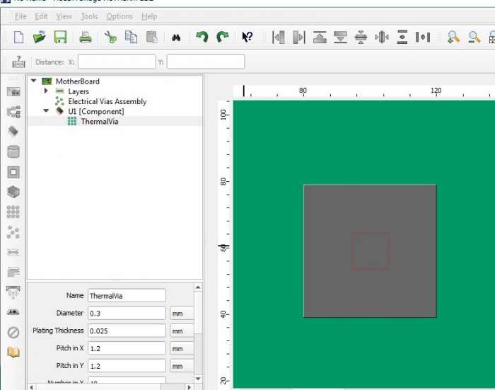
Once the board is transferred into FloTHERM, thermal vias come in as a lumped cuboid with an orthotropic conductivity. In this particular case kz = 7.03 W/(mK) and kx,y = 0.339 W/(mK)
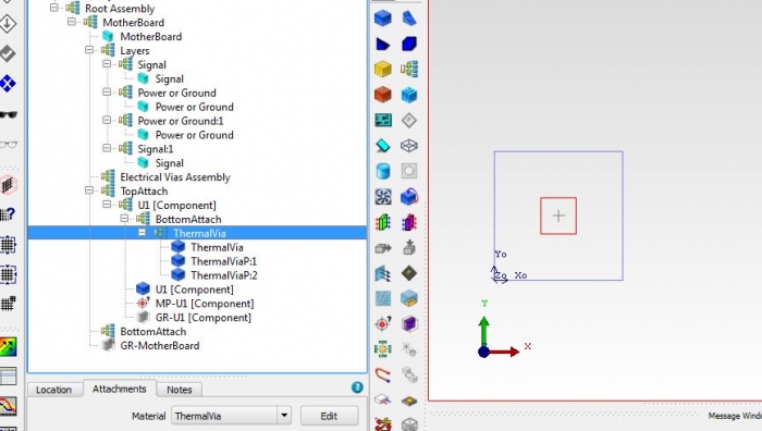
Even when not modeling the board in detail users can use the above steps to estimate the orthtropic conductivity of a lumped cuboid representing the thermal via pattern.